


Specific Machine for Crankshaft HG40/50QZ

Product Configuration
Product Overview
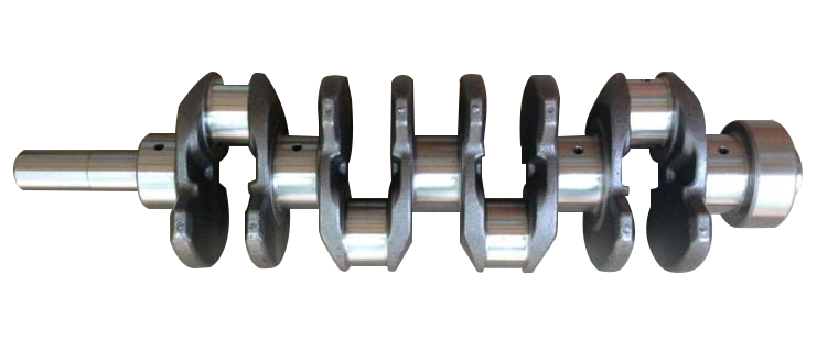
The Specific Machine for Crankshaft is a CNC Lathe designed for high-efficiency and precision machining of crankshafts, specifically developed for the manufacturing needs of the automotive, marine, and heavy machinery industries. By integrating sub-spindle collaborative control, a dedicated indexing fixture system, and synchronous rotation technology, this equipment enables complex eccentric machining of single-throw and multi-throw crankshafts, significantly improving processing efficiency and dynamic stability to meet the demands of high-precision, large-volume crankshaft production.
Features
Multi-Axis Collaboration & Dedicated Fixture System:
Equipped with a sub-spindle and crankshaft-specific indexing fixtures, enabling rapid positioning and precise clamping of multi-throw crankshafts while minimizing manual adjustments.
The indexing mechanism allows flexible angular adjustments to accommodate diverse machining requirements for single-throw to multi-throw crankshafts.
Complex Eccentric Machining Capability:
Synchronous rotation control between the main spindle and sub-spindle ensures precision turning of eccentric crankshaft sections, significantly enhancing dynamic stiffness during cutting to prevent surface defects caused by vibrations.
Supports integrated machining of crankshaft connecting rod journals, main journals, and flange end faces, delivering excellent surface finish to meet high-precision standards.
High-Rigidity Structure & Intelligent Control:
Features a high-rigidity cast iron bed combined with precision guideway systems, ensuring stability and durability under heavy cutting conditions.
Integrated intelligent CNC system supports multi-process programming and real-time monitoring, simplifying operations and enhancing automation.
High Efficiency & Flexible Adaptability:
Modular design enables quick configuration changes to adapt to crankshafts of varying specifications, reducing setup time.
Standard automated auxiliary functions (e.g., chip management) minimize manual intervention and optimize equipment utilization.
Conclusion:
It is equipped with special fixtures and indexing mechanisms for the auxiliary spindle and relevant crankshafts.The eccentric machining of single and multiple crankshafts is possible.The main shaft and auxiliary main shaft can rotate synchronously to increase the dynamic stiffness of the crankshaft during cutting.
Applications
Industries: Automotive engines, marine power systems, heavy engineering machinery, diesel engine manufacturing.
Typical Scenarios:
Automotive: Full-process precision machining of passenger/commercial vehicle engine crankshafts.
Marine: Multi-throw eccentric turning and complex contour forming of large marine crankshafts.
Engineering Machinery: High-volume production of heavy-duty crankshafts for excavators and cranes.
Energy Equipment: High-precision repair and remanufacturing of generator set crankshafts.
Technical Specifications
|
Parameter |
Name |
unit |
HG40/50QZ |
|
Bed |
Bed Configuration |
/ |
The bed base is a single unit with a standard 45° inclination |
|
X/Z Guideway Form |
/ |
Precision Linear Roller Guideways |
|
|
Working Range |
Maximum Turning Diameter On The Bed |
mm |
Φ500 |
|
Maximum Cutting Diameter |
mm |
Shaft: φ250, Disc: φ400 |
|
|
Maximum Processing Length |
mm |
500 |
|
|
Maximum Tip Distance |
mm |
590 |
|
|
Feed |
Maximum travel of X/Z-axis |
mm |
220/650 |
|
Fast moving speed of X/Z-axis |
m/min |
20/20 |
|
|
Spindle |
Spindle Head |
HSK |
A2-8 |
|
Spindle Taper |
|
100# Metric Cone |
|
|
Spindle Through-Hole Diameter |
mm |
Φ90 |
|
|
Maximum Spindle Speed |
r/min |
3000 |
|
|
Sub-spindle |
Sub-spindle Head |
HSK |
A2-5 |
|
Through-Hole Diameter |
mm |
Φ46 |
|
|
Maximum Sub-spindle Speed |
r/min |
1000 |
|
|
Chuck |
Spindle Axis |
Inch |
8″ (hollow) |
|
Sub-spindle |
Inch |
6″ (hollow) |
|
|
Turret |
Type of Turret |
/ |
100-8T |
|
Tool Holder Specification |
mm |
□25*25, Round Hole Tool Holder Φ40 |
|
|
Chip Removal |
Chip Removal Method |
|
Automatic Rear |
|
Power of Main Motor |
Spindle Servo Motor Power |
KW |
11-15 |
|
External Dimension |
Length*Width*Height |
mm |
2550*1730*1840 |
|
Weight |
kg |
4300/4700 |
|
|
Machining Accuracy |
Repetitive positioning precision X/Y |
mm |
0.003/0.005 |
|
Roundness |
mm |
0.005 |
|
|
Diameter Consistency |
mm |
0.015/300 |
|
|
Flatness |
mm |
0.015/300 (concave only) |
|
|
Surface Roughness (Aluminum/Steel) |
Ra |
0.8~1.6 |
|
|
Forms of protection |
Fully Closed Shroud |
set |
1 |
Send your message to us:
Products categories
-

CNC Vertical Turning and Milling Composite Cent...
-

High Speed Graphite CNC Machining Center GM Series
-

High Speed CNC Milling GT Series
-

Dual-Spindle CNC Lathe SK32
-

CNC Vertical Machining Center RFTV510 For Wheel...
-

CNC Vertical Machining Center RFMV Series For W...
-

CNC Vertical Lathe RFCL63V/D For Wheel Hub
-

CNC Horizontal Lathe RFCP Series for Wheel Hub
-

Specific Machine for Crankshaft HG40/50QZ
-

Specific CNC Turning and Grinding Machine HGQM-01
-

Specific Machine for Flywheel HG40/50L
-

Specific Machine for Rear Axle HGZK-06