


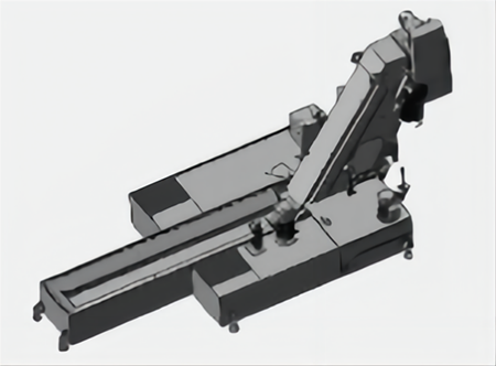
High-speed Horizontal Machining Center CW Series


Configure
Features
High-rigidity structure enables high-precision processing
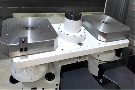
Coupling of worktable:The connection between the worktable body and the pallet is tightened by a 4-point cone with a pallet clamping force of 73.2KN. The coupling of the indexing table uses a worktable clamping force of 85.2KN to maintain stable processing of heavy cutting.
X-axis tilt design:The different installation plane heights of the X-axis linear guides ensure high rigidity and achieve high-speed and high-precision positioning.
High-precision processing design
Built-in spindle/electric spindle:The built-in spindle/motorized spindle significantly reduces vibration during high-speed operation, achieves excellent surface finish, and thus significantly extends tool life.
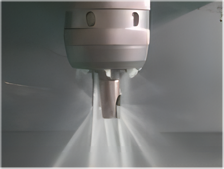
Spindle temperature control
To achieve high-precision machining, coolant is circulated through the spindle bearings and spindle box to reduce thermal changes in the spindle.
X, Y, Z axis ball screws with hollow cooling:The coolant, which is temperature-controlled by the cooling unit, circulates through the axis of the ball screw, thereby ensuring stable processing accuracy at continuous high-speed operation.
X,Y axis protection cover:The multi-section sheet metal guard with brushes is replaced by an accordion-style foldable guard. This compact design effectively controls chips and cutting fluid in the machining area.
Technical Specifications
|
Item |
Unit |
CW4000 |
CW5000 |
CW6800 |
CW8800 |
|
|
Worktable |
Worktable (L×W) |
mm |
400×400 |
500×500 |
630×630 |
800×800 |
|
|
Number of worktable |
pcs |
2 |
2 |
2 |
2 |
|
|
Max.Load of worktable |
kg |
300 |
500 |
1200 |
2000 |
|
|
Max.workpiece size of worktable |
mm |
0710*510 |
0800*1000 |
01100*1000 |
01450*1200 |
|
|
Height of worktable from ground |
mm |
1054 |
1165 |
1380 |
1400 |
|
|
Minimum division value |
° |
0.001 |
0.001 |
0.001 |
0.001 |
|
Feed |
X/Y/Z axis fast movement |
m/min |
60/60/60 |
60/60/60 |
60/60/60 |
60/60/60 |
|
|
Cutting feed speed |
m/min |
1-10 |
1-10 |
1-10 |
1-10 |
|
Travel |
X/Y/Z axis travel |
mm |
500×450×400 |
800×800×800 |
1100×900×980 |
1500×1200×1325 |
|
|
Distance from spindle center to worktable |
mm |
130-580 |
130-930 |
150-1050 |
100-1300 |
|
Spindle |
Distance from spindle end to worktable center |
mm |
125-525 |
50-850 |
150-1130 |
100-1425 |
|
|
Spindle specifications (installation diameter/transmission mode) |
mm |
170/Built-in |
250/Built-in |
300/Built-in |
300/Built-in |
|
|
Spindle taper hole |
mm |
BT40 |
BT40 |
BT50 |
BT50 |
|
|
Max.spindle speed |
r/min |
15000 |
15000 |
8000 |
8000 |
|
|
Spindle motor power |
kW |
11/15 |
15/18.5 |
18.5/30 |
18.5/30 |
|
|
Spindle motor torque |
N.m |
32/53.4 |
95.5/250 |
305/623 |
305/623 |
|
Tools |
Tool magazine capacity |
T |
23 |
50 |
40 |
40 |
|
|
Max.tool diameter/length |
mm |
110/250 |
150/500 |
250/500 |
250/500 |
|
|
Max.tool weight |
kg |
8 |
8 |
20 |
25 |
|
Three axis |
X-axis guide rail (rail Width /Number of Sliders) |
mm |
35/2 |
45/2 |
55/2 |
55/6 |
|
|
Y-axis guide rail (rail Width /Number of Sliders) |
|
35/2 |
35/2 |
55/2 |
55/2 |
|
|
Z-axis guide rail (rail Width /Number of Sliders) |
|
35/2 |
45/2 |
55/4 |
65/4 |
|
|
X-axis screw |
/ |
2R40×20 |
2R40×20 |
2R50×20 |
2R50×20 |
|
|
Y-axis screw |
/ |
2R40×20 |
2R40×20 |
2R50×20 |
2R50×20 |
|
|
Z-axis screw |
/ |
2R36×20 |
2R40×20 |
2R50×20 |
2R50×20 |
|
Accuracy |
Positioning accuracy |
mm |
±0.005/300 |
|||
|
|
Repeated positioning accuracy |
mm |
±0.003/300 |
|||
|
Other |
Air requirement |
kg/cm² |
≥6 |
|||
|
|
Gas flow |
L/min |
≥200 |
|||
|
|
Machine weight (comprehensive) |
T |
6 |
11.2 |
20 |
30 |
|
|
Machine size (L×W×H) |
mm |
1680*5510*2870 |
2785*5845*3040 |
3300*6798*3400 |
4230×8447×3440 |
Configuration Introduction
Double exchange worktable
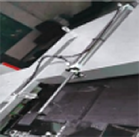
Front automatic door
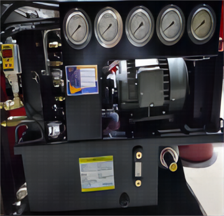
Hydraulic station
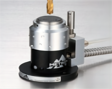
Tool setter
( Tool breakage detection system )
Chain chip conveyor
Spindle CTS
(CTS pressure 15Bar)
Processing Cases
Construction Machinery、Aerospace Industry、Automotive Industry
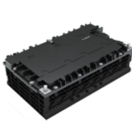
New energy battery housing
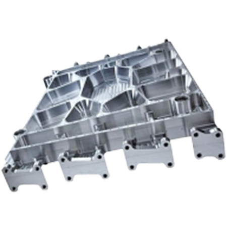
Groove Plate
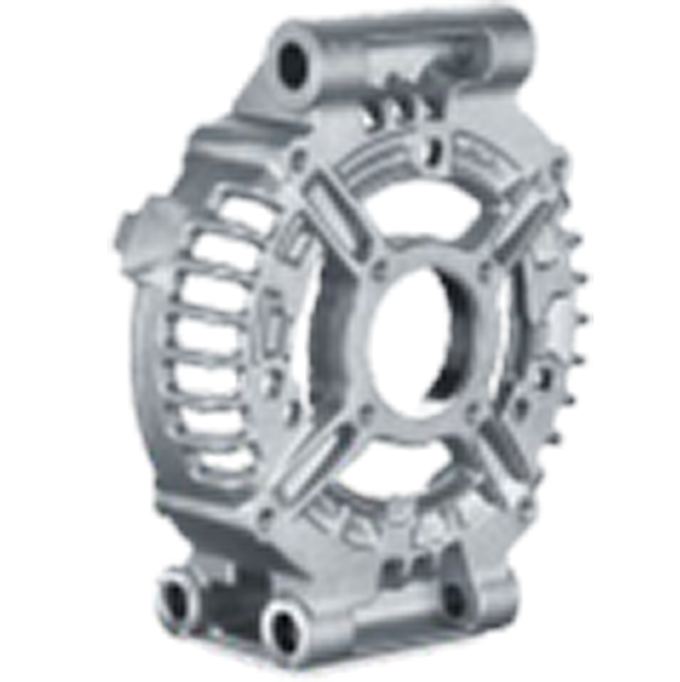
Transmission bearings
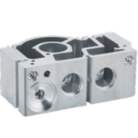
Splitter Shell
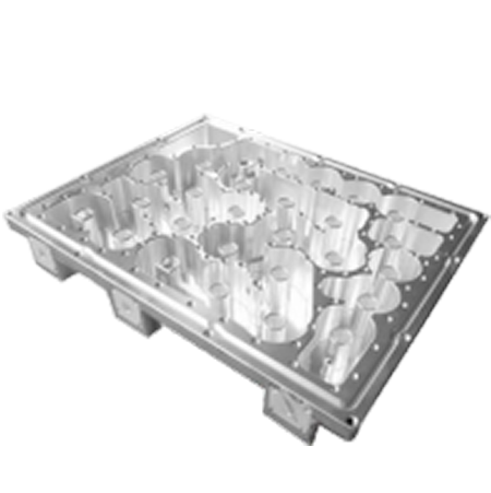
Communication cavity
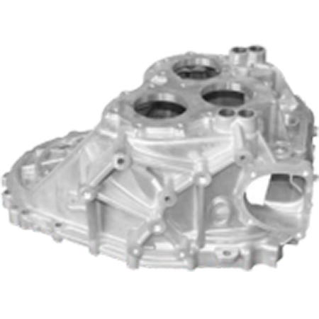
Clutch housing
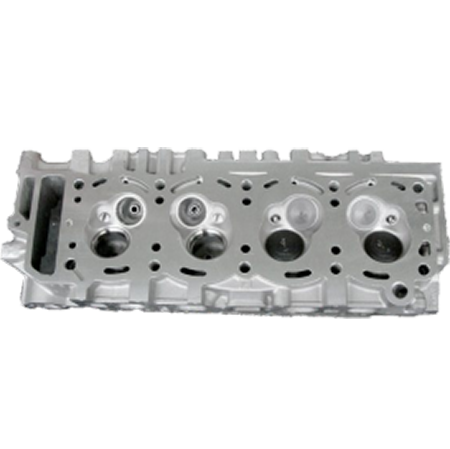
Cylinder head
Cylinder head
Send your message to us:
Products categories
-

CNC Vertical Turning and Milling Composite Cent...
-

High Speed Graphite CNC Machining Center GM Series
-

High Speed CNC Milling GT Series
-

Dual-Spindle CNC Lathe SK32
-

CNC Vertical Machining Center RFTV510 For Wheel...
-

CNC Vertical Machining Center RFMV Series For W...
-

CNC Vertical Lathe RFCL63V/D For Wheel Hub
-

CNC Horizontal Lathe RFCP Series for Wheel Hub
-

Specific Machine for Crankshaft HG40/50QZ
-

Specific CNC Turning and Grinding Machine HGQM-01
-

Specific Machine for Flywheel HG40/50L
-

Specific Machine for Rear Axle HGZK-06