CNC Profile Machining Center
CNC Profile Machining Center
CNC Drilling Machine
Machine Features
Bosm DC series CNC drilling and milling machines are mainly used for efficient drilling milling and tapping of workpieces with linear material width within the effective range. Through hole and blind hole can be drilled on single material parts and composite materials. The machine processing with CNC controller, the operation is very convenient. It can realize automation, high precision, multi variety and mass production.
In order to meet the processing requirements of different users, Our company has developed a variety of finalized products.It can also be designed and customized according to the actual needs of users.
Machine Structure
The equipment is mainly composed of bed table, mobile gantry, mobile saddle, drilling and milling power head, automatic lubrication device and protection device, circulating cooling device, digital control system, hydraulic system, electrical system, etc. The machine tool has high positioning accuracy and repeated positioning accuracy.
1. Bed &worktable:
The machine bed is welded steel structure parts, and the main frame is processed by steel structure parts. After the internal stress is removed by artificial aging heat treatment, it has good dynamic and static rigidity and no deformation. The worktable is made of casting iron HT250. The worktable can be used for clamping workpieces. It can also be equipped with pneumatic fixture, which is more convenient and fast for clamping workpieces,. The maximum bearing capacity of the worktable is 1 ton. The upper left side of the bed is vertically installed with two ultra-high bearing capacity rolling linear guide pairs and precision rack. The gantry motor is driven by AC servo system and rack system in X direction. Adjustable bolts are distributed on the bottom surface of the bed, which can easily adjust the level of the bed table.
2. Moving cantilever:
The movable cantilever gantry with cast iron structure is processed after removing internal stress by artificial aging heat treatment, with good dynamic and static rigidity and no deformation. Two rolling linear guide pairs with ultra-high bearing capacity are installed on the front and upper sides of the gantry. A linear rolling guide with ultra-high bearing capacity, a set of precision ball screw and a servo motor are installed on the top to make the slide plate of power head move in Y-axis direction. A drilling power head is installed on the slide plate of power head. The movement of the gantry is realized by the rotation of the ball screw driven by the servo motor through the coupling.
3. Moving saddle:
The movable sliding saddle is a steel structural member. Two rolling linear guide pairs with ultra-high bearing capacity, a set of precision ball screw and a servo motor are installed on the sliding saddle to drive the drilling power head to move in the z-axis direction, which can realize the fast forward, work forward, fast backward and stop of the power head. It has the functions of automatic chip breaking, chip removing and pause.
Special servo spindle motor is used for drilling power head. The special precision spindle is driven by toothed synchronous belt to realize variable frequency stepless speed change. The feed is driven by servo motor and ball screw.
The y-axis can be linked and controlled by half closed loop, which can realize linear and circular interpolation. The main shaft end is er taper hole clamping drill or milling cutter, with higher precision, high speed cutting, pneumatic tool change function, optional with hat type tool magazine, tool magazine capacity of eight, tool change is more easy, high degree of automation of manual processing.
5. Automatic lubrication device and protection device:
The machine is equipped with automatic lubrication device, which can automatically lubricate the moving pairs such as guide rail, lead screw and rack. The x-axis and Y-axis of the machine tool are equipped with dust-proof protective cover, and the waterproof splash baffle is installed around the worktable.
6. KND Control System:
6.1. With chip breaking function, chip breaking time and chip breaking cycle can be set on the man-machine interface.
6.2. With the tool lifting function, the tool lifting height can be set on the man-machine interface. When drilling to this height, the drill bit is quickly lifted to the top of the workpiece, then the chip is thrown, and then fast forward to the drilling surface and automatically converted into work advance.
6.3. The centralized operation control box and handheld unit are equipped with CNC system, USB interface and LCD screen. In order to facilitate programming, storage, display and communication, the operation interface has the functions of man-machine dialogue, error compensation and automatic alarm.
6.4. The equipment has the function of preview and recheck of hole position before machining, so the operation is very convenient.
Specification
|
Model |
BOSM-DC60050 |
|
|
Max. workpiece size |
Length × width (mm) |
2600×500 |
|
Vertical Ram drilling power head |
Quantity (piece) |
1 |
|
Spindle taper hole |
BT40 |
|
|
Drilling diameter (mm) |
Φ2-Φ26 |
|
|
Spindle speed (R / min) |
30~3000 |
|
|
Spindle power (kw) |
15 |
|
|
Distance between from spindle nose and working table (mm) |
150-650mm |
|
|
X-axis (lateral travel) |
Maximum stroke (mm) |
500 |
|
X-axis moving speed (M / min) |
0~9 |
|
|
X-axis servo motor power (kw) |
2.4*1 |
|
|
Y-axis(column longitudinal movement) |
Maximum stroke (mm) |
2600 |
|
Y-axis moving speed (M / min) |
0~9 |
|
|
Power of y-axis servo motor (kw) |
2.4*1 |
|
|
Z axis(Vertical ram feed motion) |
Maximum stroke (mm) |
500 |
|
Moving speed of Z axis (M / min) |
0~8 |
|
|
Z-axis servo motor power (kw) |
1×2.4 with brake |
|
|
Dimension of machine |
Length × width × height(mm) |
5400×2180×2800 |
|
Positioning accuracy |
X/Y/Z |
±0.05/300mm |
|
Repeated accuracy positioning |
X/Y/Z |
±0.025/300mm |
|
Gross weight(t) |
4.5 |
|
Quality Inspection
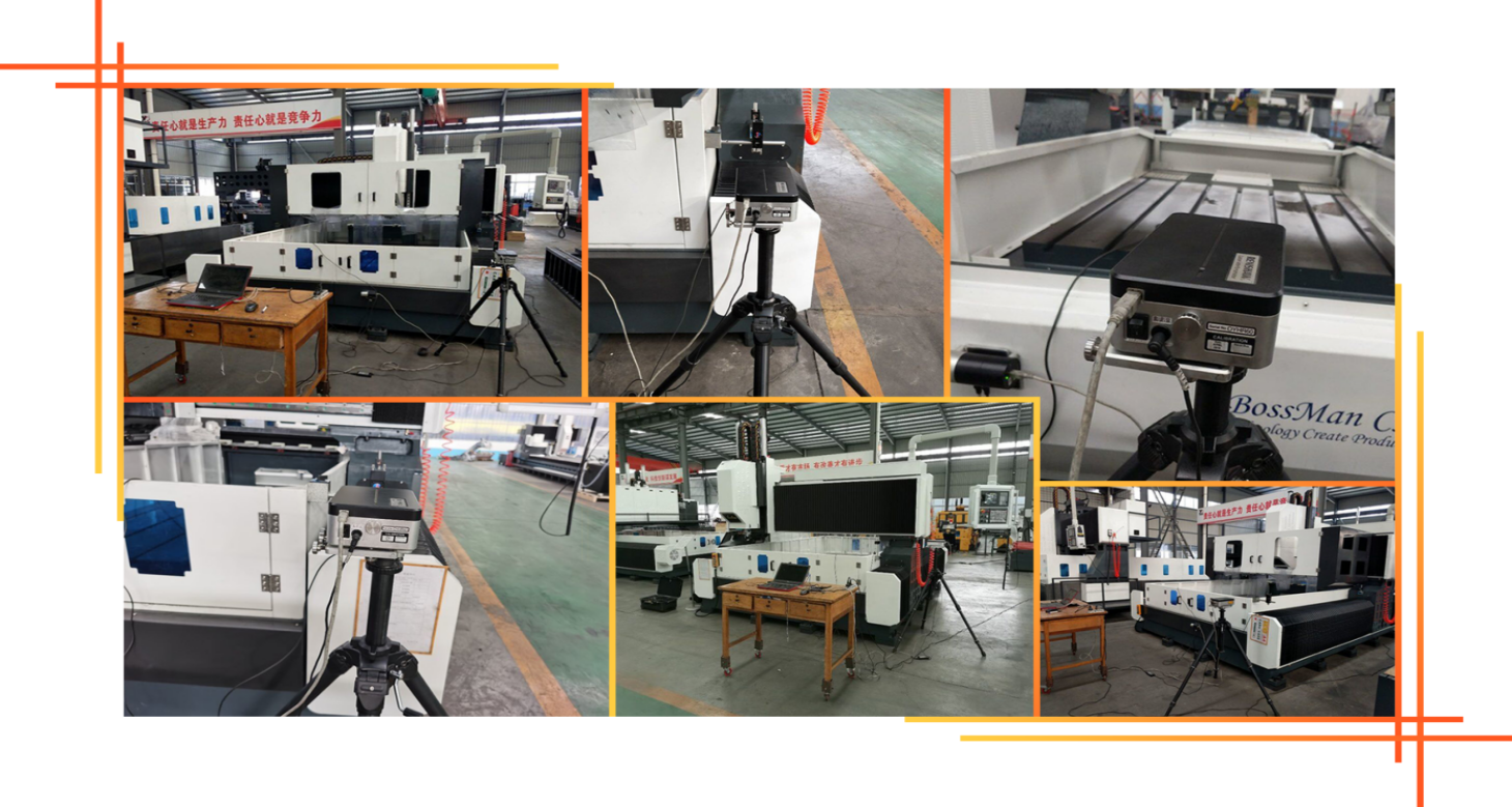
Each machine is calibrated with a laser interferometer from the United Kingdom RENISHAW company, which accurately inspects and compensates for pitch errors, backlash, positioning accuracy, and repeated positioning accuracy to ensure the machine's dynamic, static stability, and processing accuracy. . Ball bar test Each machine uses a ball bar tester from the British RENISHAW company to correct the true circle accuracy and machine geometric accuracy, and perform circular cutting experiments at the same time to ensure the machine's 3D machining accuracy and circle accuracy.
Machine tool use environment
1.1 Equipment environmental requirements
Maintaining a constant level of ambient temperature is an essential factor for precision machining.
(1) Available ambient temperature is -10 ℃ ~ 35 ℃. When the ambient temperature is 20 ℃, the humidity should be 40 ~ 75%.
(2) In order to keep the static accuracy of the machine tool within the specified range, the optimal ambient temperature is required to be 15 ° C to 25 ° C with a temperature difference
It should not exceed ± 2 ℃ / 24h.
1.2 Power supply voltage: 3-phase, 380V, voltage fluctuation within ± 10%, power supply frequency: 50HZ.
1.3 If the voltage in the use area is unstable, the machine tool should be equipped with a regulated power supply to ensure the normal operation of the machine tool.
1.4. The machine tool should have reliable grounding: the grounding wire is copper wire, the wire diameter should not be less than 10mm², and the grounding resistance is less than 4 ohms.
1.5 In order to ensure the normal working performance of the equipment, if the compressed air of the air source fails to meet the requirements of the air source, a set of air source purification devices (dehumidification, degreasing, filtering) should be added before the machine's air intake.
1.6. The equipment should be kept away from direct sunlight, vibration and heat sources, and away from high-frequency generators, electric welding machines, etc., so as to avoid machine production failure or loss of machine accuracy.
Before&After Service
1)Before Service
Through study the request and necessary information from customers then feedback to our engineers, the Bossman Technical team is responsible for the technical communication with the customers and the formulation of solutions, assisting customer in selecting the appropriate machining solution and suitable machines.
2)After Service
A.The machine with one-year warranty and paid for life-long maintenance.
B.During the one-year warranty period after the machine arrived in destination port, BOSSMAN will provide free and timely maintenance services for various non-man-made faults on machine, and timely replace all kinds of non-man-made damage parts free of charge . Failures occurring out the warranty period shall be repaired at appropriate charges.
C.Technical support in 24 hours online, TM, Skype, E-mail, solving the relative questions in time. if cannot be resolved,BOSSMAN will immediately arrange for after-sales engineer to arrive on-site for repair,buyer need pay for the VISA, flights tickets and accommodation.
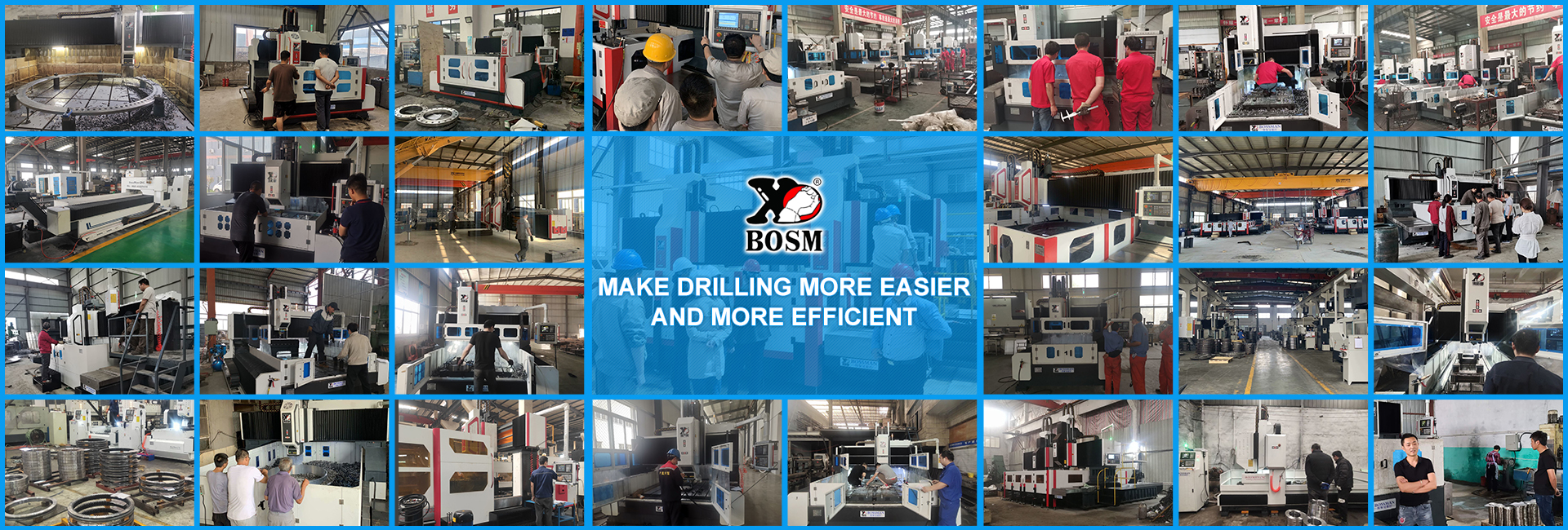
Customer’s Site


