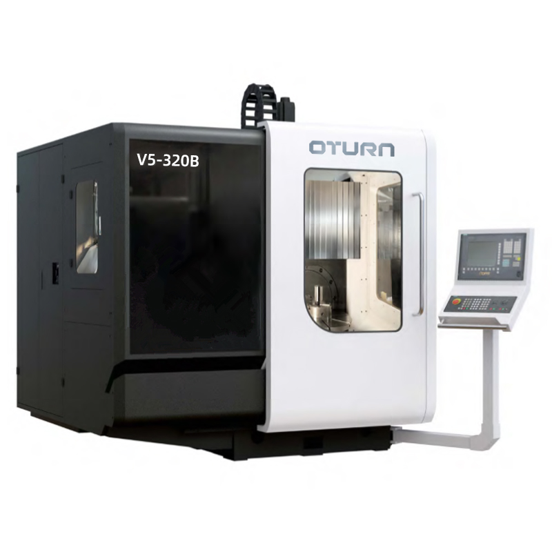
5-Axis Vertical Machining Center V5-320B
1. Overall layout of the machine tool
The V5-320B five-axis machining center adopts a stable C-shaped structure, the column is fixed on the bed, the slide plate moves horizontally along the column (X direction), the slide seat moves longitudinally along the slide plate (Y direction), and the headstock moves vertically along the slide seat ( Z direction). The working table adopts the self-developed direct-drive single-arm cradle structure, and its various performance indicators have reached the international advanced level.
2. Feed system
X, Y, Z-axis linear guide rails and ball screws, small dynamic and static friction, high sensitivity, small high-speed vibration, no creeping at low speed, high positioning accuracy, and excellent servo drive performance.
X, Y, Z-axis servo motors are directly connected with high-precision ball screws by couplings, reducing intermediate links, realizing gapless transmission, flexible feeding, accurate positioning, and high transmission precision.
The Z-axis servo motor has a brake function. In the event of a power failure, the brake can automatically hold the motor shaft tightly so that it cannot rotate, which plays a role of safety protection.
3. Electric spindle
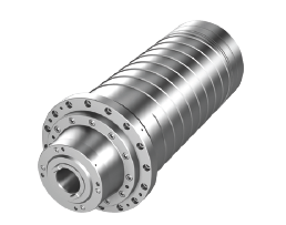
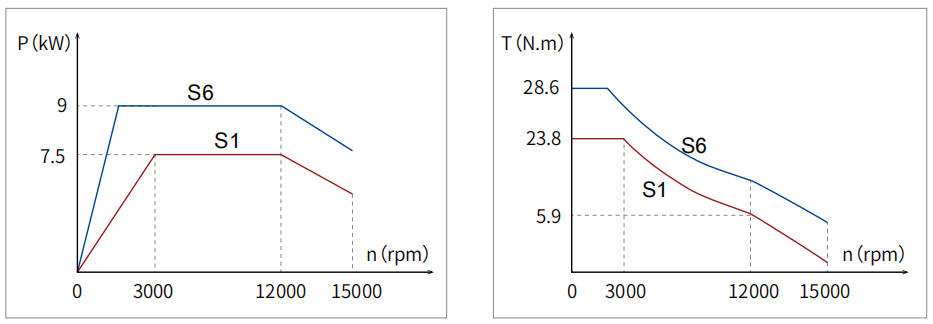
The electric spindle adopts the self-developed high-performance electric spindle (invention patent: 202010130049.4), and the end is equipped with cooling nozzles to cool the tool. It has the advantages of high speed, high precision, and high dynamic response, and can realize stepless speed regulation. Built-in High-precision encoder can realize directional accurate stop and rigid tapping.
4. Tool magazine
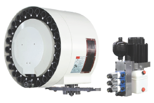
BT40 disc type tool magazine, 24 tool positions, automatic tool change by ATC manipulator.
See below:
5. Turntable
It adopts the self-developed direct-drive single-arm cradle structure, which has the advantages of high rigidity, high precision and high dynamic response.
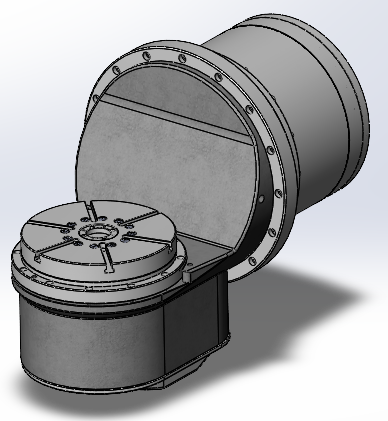
| Axis | Rated Torque Nm | Rated Speed rpm | Max. Speed rpm | Rated Current A | Rated Power kW |
| B | 656 | 80 | 100 | 18 | 5.5 |
| C | 172 | 100 | 130 | 6.1 | 1.8 |
6. Fully closed loop feedback system
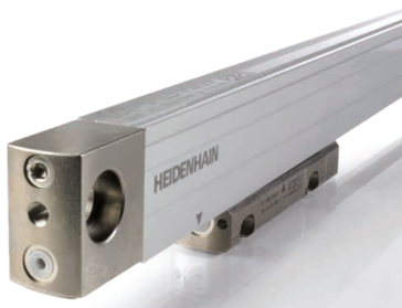
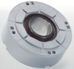
X, Y, and Z linear axes are equipped with HEIDENHAIN LC4 series absolute value grating scales; B and C rotary tables are equipped with HEIDENHAIN RCN2000 series absolute value angle encoders to realize full-closed-loop feedback of 5 feed axes, ensuring that the machine tool has high precision and high precision. accuracy retention.
7. Cooling and pneumatic system
Equipped with a water cooler for constant temperature cooling to ensure that the electric spindle and direct drive turntable are in good working condition and can run efficiently for a long time.
The pneumatic system is filtered by pneumatic components to realize the functions of cleaning and blowing the taper hole of the main shaft, air sealing protection of the main shaft bearing, and turning over of the tool magazine and tool holder.
8. Centralized lubrication system
The slide block of the guide rail and the nut of the ball screw adopt a centralized lubricating device with thin grease, which provides regular and quantitative lubrication to ensure the accuracy and stability of the ball screw and guide rail.
9. Workpiece measuring system
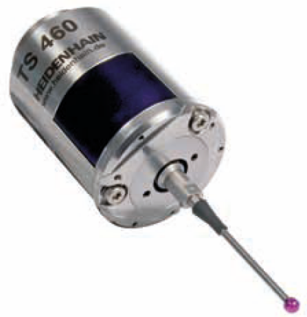
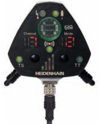
The machine tool is equipped with HEIDENHAIN TS460 touch probe and wireless signal receiver, which can be installed on the spindle through manual or automatic tool change system to realize the functions of workpiece alignment, workpiece measurement and preset point setting, and the measurement repeatability is ≤1um (probing speed 1 m/min), the working temperature is 10°C to 40°C. The HEIDENHAIN touch probe is triggered by an optical switch. The stylus uses a three-point bearing to ensure the ideal free state position. It is wear-free during use, has consistent repeatability and is stable for a long time.
10. Tool measuring system
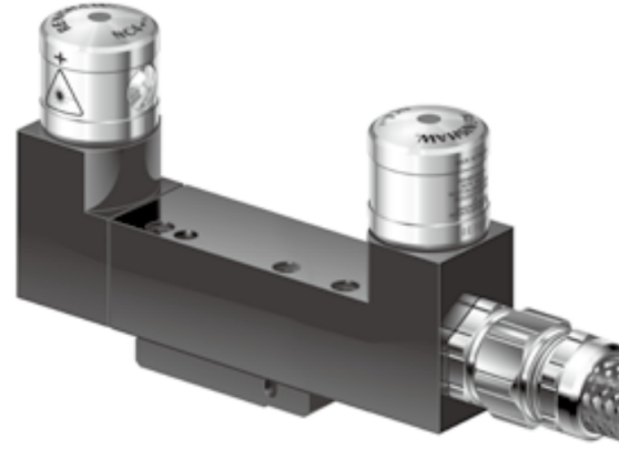
The machine tool is equipped with Renishaw NC4 laser tool setting instrument, the measurement repeatability is ±0.1um, and the working temperature is 5°C to 50°C.
11. Five-axis precision calibration
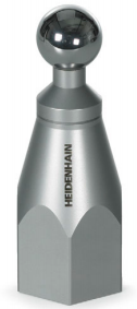
The machine tool is equipped with KKH calibration balls from HEIDENHAIN, together with TS series probes, to achieve precision calibration of machine tool rotation axis, reduce errors during machine tool movement, and achieve high precision and high repeatability.
12. Machine tool protection
The machine tool adopts an integral protective cover that meets safety standards to prevent coolant and chips from splashing, ensure safe operation, and have a pleasant appearance. The X direction of the machine tool is equipped with an armor shield, which can effectively protect the guide rail and ball screw.
13. Machine tool working conditions
(1) Power supply: 380V±10% 50HZ±1HZ three-phase AC
(2) Ambient temperature: 5°C-40°C
(3) Optimum temperature: 22°C-24°C
(4) Relative humidity: 20-75%
(5) Air source pressure: ≥6 bar
(6) Gas source flow rate: 500 L/min
14. Function introduction of CNC system
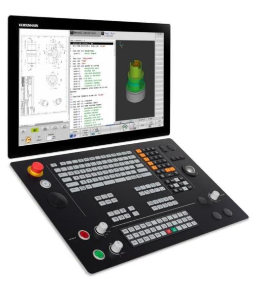
HEIDENHAIN TNC640 CNC system
(1) Number of axes: up to 24 control loops
(2) Touch screen version with multi-touch operation
(3) Program input: Klartext conversational and G code (ISO) programming
(4) FK free contour programming: use Klartext conversational programming language to perform FK free contour programming with graphic support
(5) Abundant milling and drilling cycles
(6) Tool compensation: tool radius compensation and tool length compensation. Probe cycle
(7) Cutting data: Automatic calculation of spindle speed, cutting speed, feed per blade and feed per circle
(8) Constant contour processing speed: relative to the path of the tool center / relative to the tool edge
(9) Parallel Run: Program with graphics support while another program is running
(10)Contour elements: straight line/chamfer/arc path/circle center/circle radius/tangentially connected arc/rounded corner
(11) Approaching and departing from contours: tangential or perpendicular/through arc paths
(12) Program jump: subroutine/program block repeat/any program can be a subroutine
(13) Canned cycle: drilling, tapping (with or without floating tapping frame), rectangular and arc cavity. Peck drilling, reaming, boring, spot facing, spot drilling. Milling internal and external threads. Roughing of flat and inclined surfaces. Complete machining of rectangular and circular pockets, rectangular and circular bosses. Roughing and finishing cycles for straight and circular grooves. Array points on circles and lines. Array point: QR code. Contour chain, Contour pocket. Contour groove for trochoidal milling. Engraving cycle: engrave text or numbers along a straight line or arc.
(14) Coordinate transformation: translation, rotation, mirroring, scaling (specific axis).
(15) Q parameter variable programming: mathematical function, logical operation, parenthesis operation, absolute value, constant þ, negation, integer or decimal, circle calculation function, text processing function.
(16) Programming aids: calculator. A list of all current error messages. Context-sensitive help function for error messages. TNCguide: integrated help system; the TNC 640 displays information directly from the user manual. Graphical support for cycle programming. Comment blocks and main blocks in NC programs.
(17) Information acquisition: directly use the actual position in the NC program.
(18) Program verification graphics: Graphical simulation of machining operations can be performed even when another program is running. Top view/three-dimensional view/stereo view, and inclined processing plane/3-D line drawing. Local scaling.
(19) Programming graphics support: Even if another program is running, the graphics (2-D handwriting tracing diagram) of the input NC program segment can be displayed in the program editing operation mode.
(20) Program running graphics: real-time graphics simulation while executing the milling program. top view/three view/stereo view.
(21) Processing time: Calculate the processing time in the "test run" operating mode. Displays the current machining time in the "Program Run" operating mode.
(22) Return to contour: display the current processing time in the "program running" operation mode. Program interruption, leaving and returning to the contour.
(23) Preset point management: a table for saving any preset point.
(24) Origin table: multiple origin tables, used to save the relative origin of the workpiece.
(25) 3-D Machining: Motion Control of High Quality Smooth Jerk
(26) Block processing time: 0.5 ms
(27) Input resolution and display step: 0.1 μm
(28) Measuring cycle: probe calibration. Manual or automatic compensation of workpiece misalignment. Set preset points manually or automatically. Tool and workpiece can be measured automatically.
(29) Error compensation: linear and nonlinear axis error, backlash, reverse sharp angle of circular motion, reverse error, thermal expansion. static friction, sliding friction.
(30) Data interface: RS-232-C/V.24, up to 115 kbit/s. Extended data interface of LSV2 protocol, use HEIDENHAIN TNCremo or TNCremoPlus software to remotely operate TNC through this data interface. 2 x Gigabit Ethernet 1000BASE-T interface. 5 x USB ports (1 front USB 2.0 port, 4 USB 3.0 ports).
(31) Diagnosis: Self-contained diagnostic tools for quick and convenient troubleshooting.
(32) CAD reader: display standard CAD format files.
Main parameter
|
Item |
Unit |
Parameter |
|
|
Worktable |
worktable diameter |
mm |
320 |
|
Maximum horizontal load |
kg |
150 |
|
|
Maximum vertical load |
kg |
100 |
|
|
T-slot |
mm |
8X10H8 |
|
|
Processing range |
Distance between spindle end face and worktable end face (Max) |
mm |
430 |
|
Distance between spindle end face and worktable end face (Min) |
mm |
100 |
|
|
X axis |
mm |
450 |
|
|
Y axis |
mm |
320 |
|
|
Z axis |
mm |
330 |
|
|
B axis |
° |
-35°~+ 110° |
|
|
C axis |
° |
360° |
|
|
Spindle |
Taper(7 ∶ 24) |
|
BT40 |
|
Rated speed |
rpm |
3000 |
|
|
Max. speed |
rpm |
15000 |
|
|
Rated torque S1 |
N.m |
23.8 |
|
|
Rated Power S1 |
KW |
7.5 |
|
|
Axis |
X axis Rapid traverse speed |
m/min |
36 |
|
Y axis Rapid traverse speed |
m/min |
36 |
|
|
Z axis Rapid traverse speed |
m/min |
36 |
|
|
B axis Max. speed |
rpm |
130 |
|
|
C axis Max. speed |
rpm |
130 |
|
|
Tool magazine |
Type |
|
Disc type |
|
Tool selection method |
|
Bidirectional nearest tool selection |
|
|
Capacity |
T |
24 |
|
|
Max. tool length |
mm |
150 |
|
|
Max. tool weight |
kg |
7 |
|
|
Max. cutter disc diameter(Full Tool) |
mm |
80 |
|
|
Maximum cutter disc diameter (Adjacent empty tool) |
mm |
150 |
|
|
Accuracy |
Executive standard |
|
GB/T20957.4(ISO10791-4) |
|
X-axis/Y-axis/Z-axis positioning accuracy |
mm |
0.008/0.008/0.008 |
|
|
B-axis/C-axis positioning accuracy |
|
7”/7” |
|
|
X-axis/Y-axis/Z-axis repeat positioning accuracy |
mm |
0.006/0.006/0.006 |
|
|
B-axis/C-axis repeat positioning accuracy |
|
5”/5” |
|
|
Machine weight |
Kg |
5000 |
|
|
Total electrical capacity |
KVA |
45 |
|
Standard Configuration List
|
No. |
Name |
|
1 |
Main components (including bed, column, slide plate, slide seat, headstock) |
|
2 |
X, Y, Z three-axis feed system |
|
3 |
Single arm cradle turntable |
|
4 |
Electric spindle BT40 |
|
5 |
Electrical control system (including electrical cabinet, power supply module, servo module, PLC, operation panel, display, handheld unit, electric cabinet air conditioner, etc.) |
|
6 |
Grating scale: HEIDENHAIN |
|
7 |
Hydraulic system |
|
8 |
Pneumatic system |
|
9 |
Centralized lubrication system |
|
10 |
Chip conveyor, water tank, chip collector |
|
11 |
Rail guard |
|
12 |
Machine tool overall protective cover |
|
13 |
Workpiece measuring device: HEIDENHAIN TS460 |
|
|
Linear scales HEIDENHAIN |
|
14 |
Tool setting instrument: HEIDENHAIN NC4 |
|
15 |
Five-axis precision calibration: HEIDENHAIN KKH |
|
16 |
Based on one point of use of HPMILL post-processing software, bind the physical address of the computer |
|
17 |
Spindle thermal elongation compensation function |
